Pelton Turbine( impulse turbine )
Pelton turbine (impulse turbine) is a hydro turbine that uses the kinetic energy of a high-pressure jet stream to perform work. The water from a high water head reservoir is led to the turbine through a penstock pipe. The high-pressure water passes through the turbine nozzle and becomes a high-speed jet of water, rushing to the bucket of the Pelton runner to make the turbine rotate in mechanical energy.
There are three types of impulse turbines, Pelton turbine, Turgo turbine, and cross-flow turbine. This column introduces the more commonly used Pelton turbines.
Structure of Pelton turbine
Figure 1 is a small and medium-sized impulse turbine model, which is mainly composed of lower casing, upper-casing, runner (in the casing), water inlet pipe, spray needle and driving mechanism, and concrete foundation.
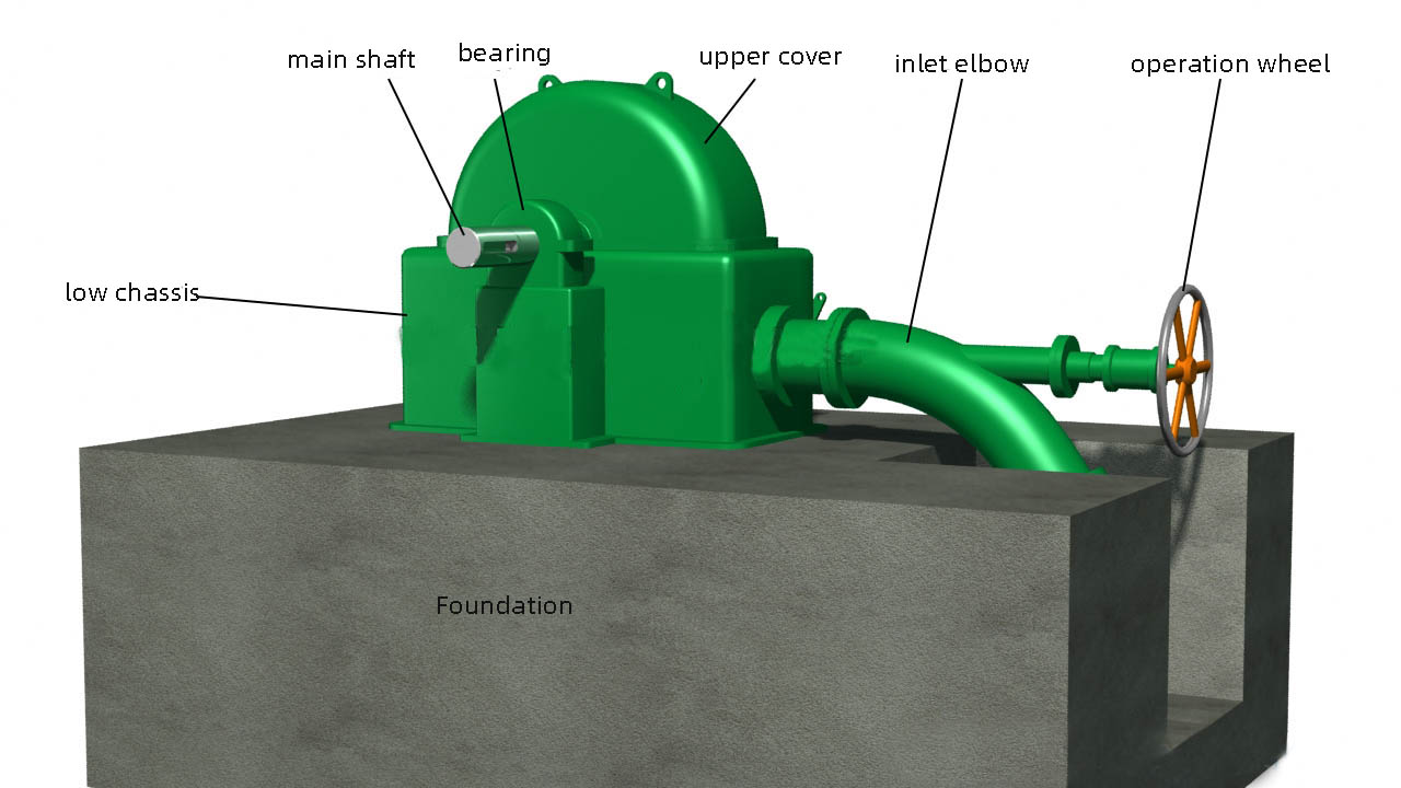
Figure 1-Appearance of impulse turbine
Open the lower casing and the upper-casing to see the runner, nozzle and deflector, as shown in Figure 2. Cut the concrete foundation to see the tail flume and the water outlet.
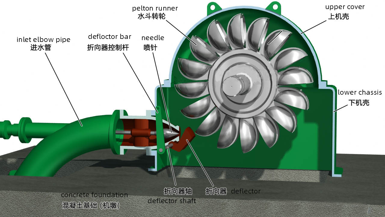
Figure 2. cross-section of pelton turbine
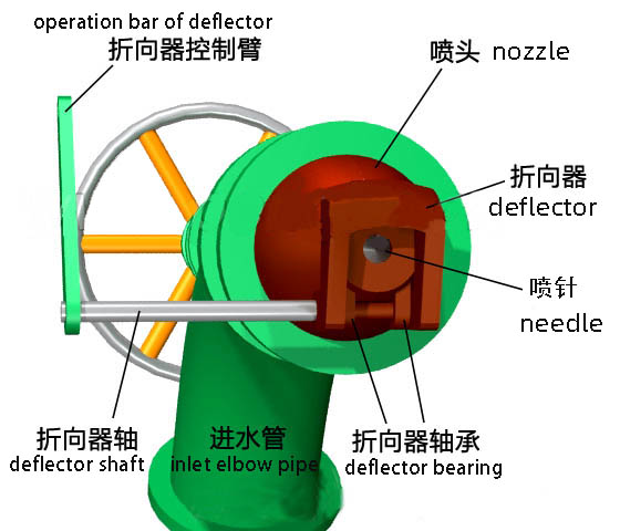
Figure 3 structural of the Nozzle
The deflector is in front of the nozzle, the axis of the deflector passes through the bearing under the nozzle, the deflector can rotate around the axis.
Multi-nozzle bucket water turbine
In order to improve the performance of water turbines, large cut-off turbines often have 2 to 6 nozzles. Figure 5 is a schematic diagram of the structure of a cut-off turbine with two nozzles.

horizontal shaft two nozzles pelton turbine

vertical shaft six nozzles Pelton turbine
Pelton Runner and working principle

Figure 4
Figure. 4 shows the runner of an impulse turbine, the left side is a front view, and the right side is a side view. The runner is composed of a roulette and multiple buckets, so it is also called bucket type turbine.
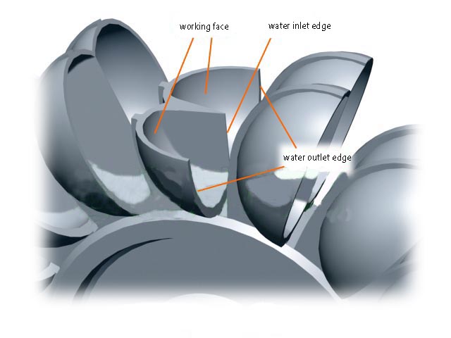
Figure 5
Figure 5 is a cross-sectional view of a water bucket. From the cross-section of a water bucket, it can be seen that the water bucket is composed of two spoon-shaped bodies side by side, and the water jet is sprayed into the two spoon-shaped bodies to push the runner to rotate.

Figure 6
Figure 6 is the working principle diagram of the impulse turbine. The high-speed water flow is sprayed to the water bucket through the nozzle, and is reflected by the water bucket to flow out. The kinetic energy of the water pushes the water bucket to realize the rotation of the runner. The blue line indicates the water jet from the nozzle and the water reflected from the runner.
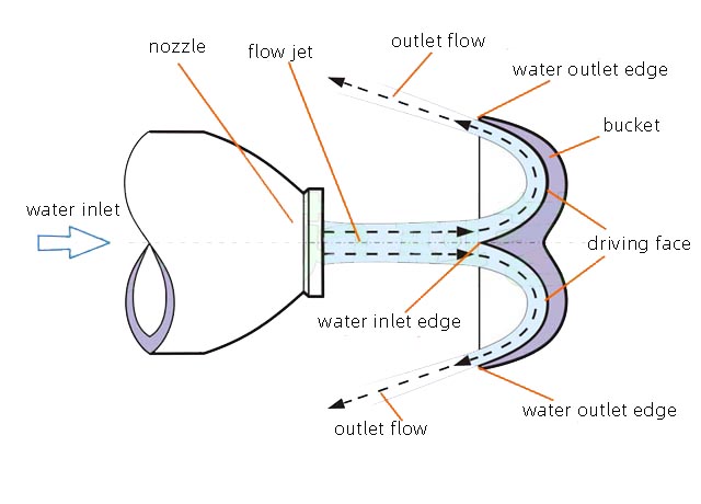
Figure 7
Figure 7 is a flow diagram of the water jet to the water bucket. The high-speed water jet from the nozzle is jetted to the water bucket. The high-speed jet of water flows through the reflection of the water bucket and transmits the kinetic energy to the water bucket to push the water bucket forward.
Jet mechanism
The jet mechanism is abbreviated as the nozzle, which is mainly composed of a nozzle, a spray needle, and a spray needle moving mechanism. The nozzle outlet size is changed by the movement of the spray needle in the nozzle, thereby changing the water flow rate of the nozzle to change the power of the water turbine.
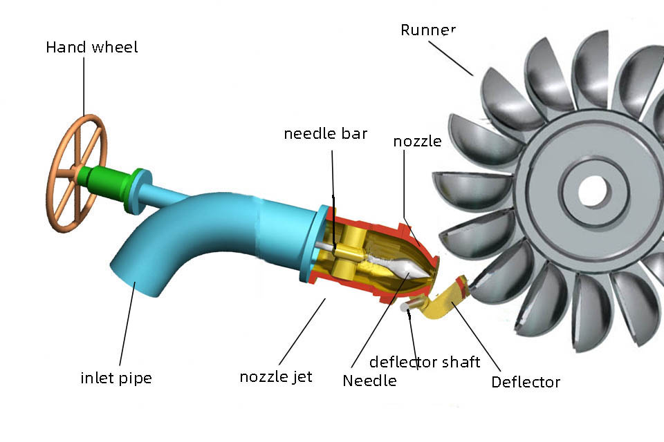
Fig. 8 is a schematic diagram of the structure of the spraying mechanism
The movement of the spray needle is completed by the spray needle moving mechanism. The picture shows the manual control of the spray needle movement. You can move the spray needle by turning the hand wheel and change the nozzle water flow; large hydraulic turbines use hydraulic or electric servo mechanism to move the spray needle. The moving mechanism is installed outside the tube, which is an external control spray mechanism.
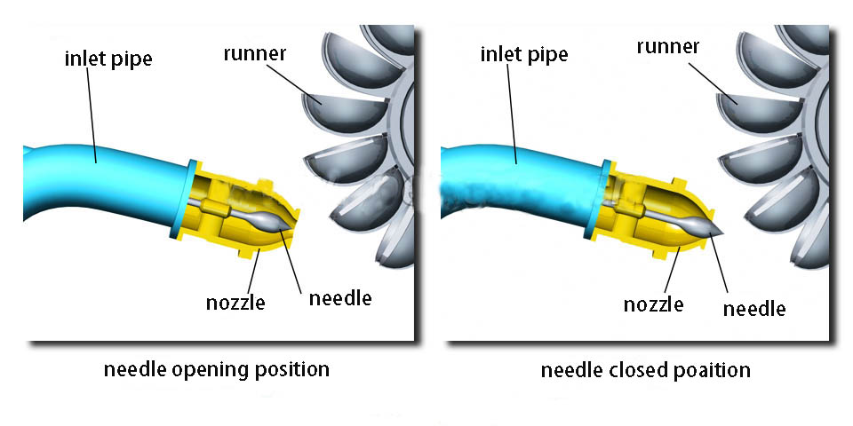
Figure 9
Figure 9 left, the needle is in the normal working position, and the water jet is directed to the water bucket. Figure 9 right, the needle moves forward to withstand the nozzle opening, and the nozzle is in the closed state.
Deflector
The impulse turbine is a high-head turbine with a head range of 100 meters to more than 1000 meters. The pipelines from the reservoir to the turbine are as long as kilometers to thousands of meters, and these pipelines have to withstand great water pressure, especially near the bottom. In the event of a grid fault trip, the water source must be shut down immediately, otherwise the turbine loses its load and the speed rises rapidly and damages the unit. Due to the length of the pipeline, it is impossible for a large amount of moving water in the pipeline to stop flowing quickly, it it the water Hammer. If the pipeline is closed quickly, it will generate extreme water pressure, which will seriously endanger the safety of the pressure pipeline. The only way is to turn the direction of the water that sprayed to the runner, instead of shutting off the water flow.
It is the easiest way to install a deflector in front of the nozzle. When the deflector is raised during normal operation, the water flow from the nozzle will not be affected. The turbine runs normally (Figure 10 left).
When the deflector is in action, the nozzle will spray The water flow is blocked by the deflector and turned to the lower outlet (right in Figure 10), and the turbine stops running. The deflector can be turned to the blocking position within 1 to 2 seconds.
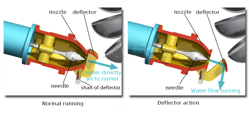
Figure 10. Working principle of the deflector
The Running principle of pelton turbine


Leave a comment