
Francis turbine is a reaction turbine. The water flow of Francis turbine enters the runner radially and leaves the runner axially, pushes the runner when passing through the blades in the axial direction, and also pushes the runner when passing downwards through the blades. That is to say, the water does work when passing through the blades in the radial and axial directions, so it is called a Francis turbine, also known as a radial axial flow turbine.
Francis turbines can be used in a wide range of heads, and there are corresponding products for use with heads ranging from 30m to 300m.
Composition and structure of Francis turbine
The basic composition of the Francis turbine will be introduced below. The main parts of the turbine are assembled around the stay ring, There is a bottom ring and draft tube under the stay ring, and a head cover above the stay ring, A spiral case is installed on the outside of the stay ring, A number of guide vanes are installed on the inside of the stay ring, A runner is installed in the middle. The guide bearing of the runner is installed on the head cover. There is a shaft sealing device under the guide bearing to prevent water from leaking into the head cover along the shaft. The gap between the upper crown and the head cover of the runner is very small, and the gap between the lower ring and the bottom ring of the runner is also very small, There is a leak-proof ring in between to ensure the free rotation of the runner and prevent water leakage from affecting the efficiency of the turbine.
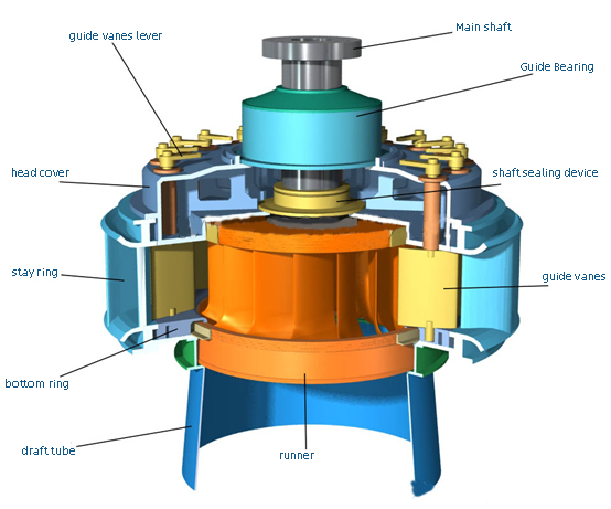
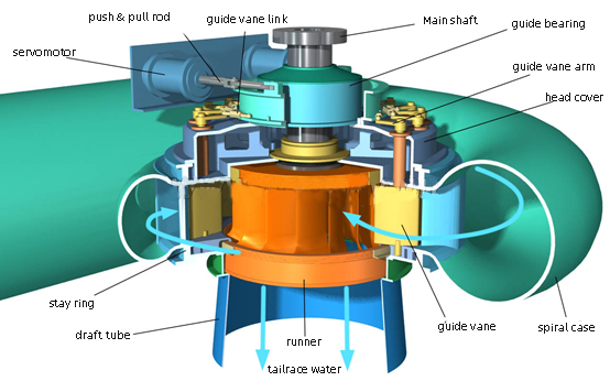
The guide vanes are installed between the head cover and the bottom ring, the guide vane shaft passes through the head cover and are connected to the distributor, and the control ring and the servomotor are installed above the head cover to form the distributor. the main shaft will be connected with generator.
In the figure, the light blue arrow line indicates the direction of the water flow through the turbine. The water enters the turbine from the inside of the volute and enters the runner through the guide vanes to form a circular flow toward the center. After the runner is pushed to rotate and perform work, it is discharged from the draft tube below.
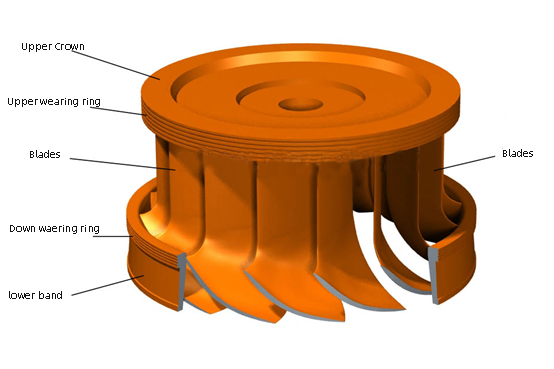
The structure of the runner of the Francis turbine
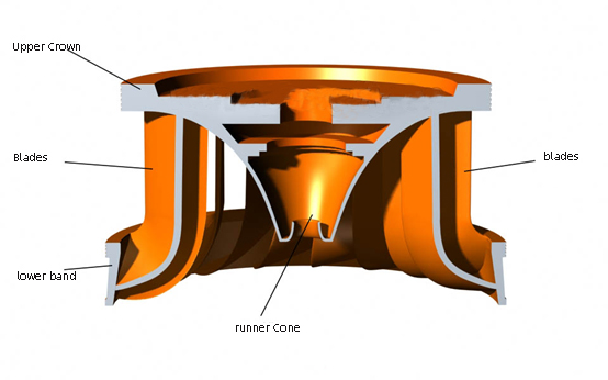
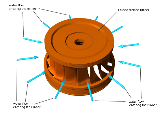
The following figure is a 3D structure diagram of the Francis turbine runner model. Multiple blades are fixed on the cone under the upper crown, and the lower end of the blade is fixed on the inner side of the lower ring.
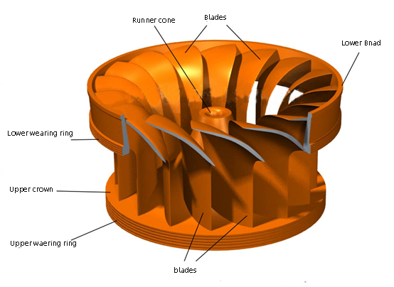
The following figure is a 3D view of the axial section of the runner. There is a drain cone under the upper crown. The upper crown and the drain cone form a smooth curved surface to allow water to flow smoothly.
Water flows horizontally from all sides into the runner of a Francis turbine
Working principle of Francis runner
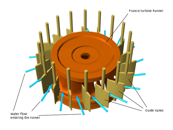
In a hydraulic turbine, the water flow enters the runner through movable guide vanes, which are distributed around the runner, as shown in the following Figure. The guide vanes control the size and direction of the water flow.
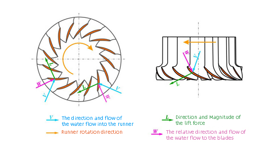
The shape of the blades of the Francis turbine runner is such that all the water flowing through the blade can push the runner to rotate, which conforms to the lift force principle of the airfoil.
Following Figure is the lift force diagram of the blades of the Francis turbine runner, which can clearly illustrate the force state of the runner blades. The arrow line in the figure shows the state of the blades generating lift force under the action of water flow. The picture on the left is the lift force diagram of the water flow entering from the upper part of the runner. The water flow basically flows radially toward the center, showing the force of the two blades. The force of the other blades is the same; the picture on the right is from the lower part of the runner. The water flow lift diagram of, the water flow basically flows downward in the axial direction, showing the force of one blade, and the force of the other blades is the same.
According to the range of water head, the runner of Francis turbine has many shapes. From the outside, it is mainly reflected in the difference between the diameter of the outer end of the blade root Ds and the diameter D2 at the outlet, which is different from the height b of the blade, which also causes the water flow to be different relative to the blade, The following Figure is a projection view of several main runner axes, the blue arrow line indicates the direction of the water flow.

(a) The figure is suitable for high water head and small flow. The runner blade height is small, and the blade is long in the horizontal direction. The water flow is mainly in the horizontal direction when passing through the blade;
Figure (b) is suitable for medium head and medium flow. The water flow passes through the blade obliquely;
Figure (c) is suitable for medium and low water head, medium and large flow. The water entering under the runner mainly passes through the blade axially, and the water entering above the runner passes through the blade in an approximately horizontal direction.
Figure (d) is suitable for low water head, large flow, the runner blades are high, the blades are short in the horizontal direction, and the water flow mainly passes through the blades in the axial direction.
Note: The blade height length and flow rate mentioned above are for comparison with runners of the same size. The number of blades of the Francis turbine runner is 9 to 21.
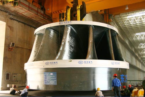
Photo of Francis turbine runner of the Three Gorges Hydropower Station

As its name states, EETS was begun as a \’club\’, and it retains certain features of that even now. It has no physical location, or even office, no paid staff or editors, but books in the Original Series